–
March 19, 2013
March 17, 2013
Floating Phrases
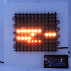
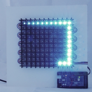
These words display in a series of 12 screens: “What is it that drives humanity to create art? Perhaps emotions find voices in time and space when we make art. Perhaps I can find the time to create art.” Then patterns flash through cut-out letters to create geometric graphics.
Adapting a Word Clock
Our class assignment was to create a project with an arduino micro-controller and LED or L-wire lights. I began with two meters of LED strips from Adafruit and an idea that originated with an $1100 word clock on Biegert & Funk’s ClockTwo website. Instead of using RGB LEDs to create words for the time of day, I used them to create dialog about art. This is a first step. I can change the text and the Arduino programming to re-purpose the project for my senior gallery installation. I’m considering using the mirrored frame for the title of my gallery exhibit.
Project components:
1) 12″ shadow box frame, with glass and backing
2) two-way acrylic mirror
3) black vinyl text cut-out that was mounted onto clear acrylic
4) translucent white acrylic panel, used to diffuse the LEDs
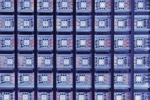
5) laser-cut black acrylic grid pieces that were assembled to isolate individual LEDs; laser patterns are attached:
vertical_acrylic_pieces
horizontal_acrylic_pieces
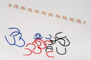
6) electronics board (white dry erase board) with ten mounted RGB LED strips, soldered wire connections between the strips, and a soldered power harness
7) Arduino pin connection to individually address 110 LEDs
8) black foam core spacer
9) Arduino Mega micro-controller and project box
10) 5-volt 10 amp power supply with a barrel plug
Programming the light sequences and uploading the code to the Arduino Mega (from SparkFun Electronics) were the final steps. With more time, I could condense some of the code, but my priority was meeting a critique deadline. Here’s the code that also includes an Arduino RAM check that is viewed on the serial monitor: project_code


